Sensors
- Sensors
- Potentiometer
- Light Sensor
- Distance Sensor
- Pressure Sensor
- Piezo Vibration Sensor
- Capacitive Sensor
- Knitted Stretch Sensor
Potentiometer
#About potis
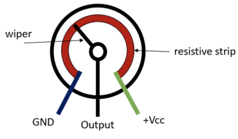
A potentiometer is a manually adjustable variable resistor with three pins. Also known as a "pot" or "poti", it consists of a resistive element (carbon, cermet, or plastic) and a sliding contact (wiper) that moves to change resistance, allowing it to regulate volume, light dimming, and speed.
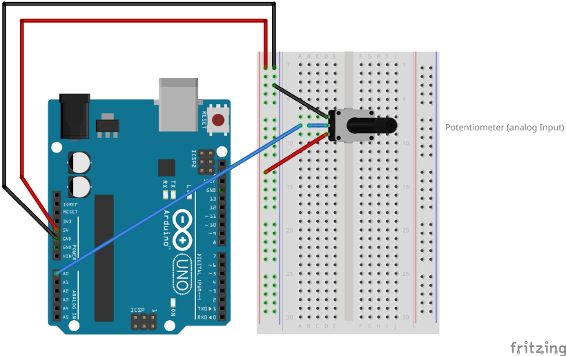
#Wiring a poti
Front view:
Left Pin -> GND
Middle Pin -> Analog Pin
Right Pin -> VCC/ 5V/3V
#Coding a poti
In Arduino open the example code File>Examples>01.Basics>AnalogReadSerial. Adjust your analog pin (A0-A5) if necessary. Upload the code and open the Serial Monitor. You should be able to read the changing values of the potentiometer when turning it.
Light Sensor
#About LDRs
A photoresistor or photocell or light-dependent resistor (LDR) is a light-controlled variable resistor. The resistance of an LDR decreases with increasing light intensity.
In general you can use a 10kOhm resistor with an LDR.
How do you know?
Hold each end of the voltmeter (resistance setting) to one of the LDR legs and move the LDR from light to dark. You should see the value changing. Pick a resistor that is equal or less than the LDR to get a usable output.
E.g.: for a 10kOhm LDR use a 1kOhm to 10kOhm resistor.
Available in the LAB: LDR1 = ca 2-10kOhm and LDR 2 = ca 1.5-7kOhm.
#Wiring an LDR
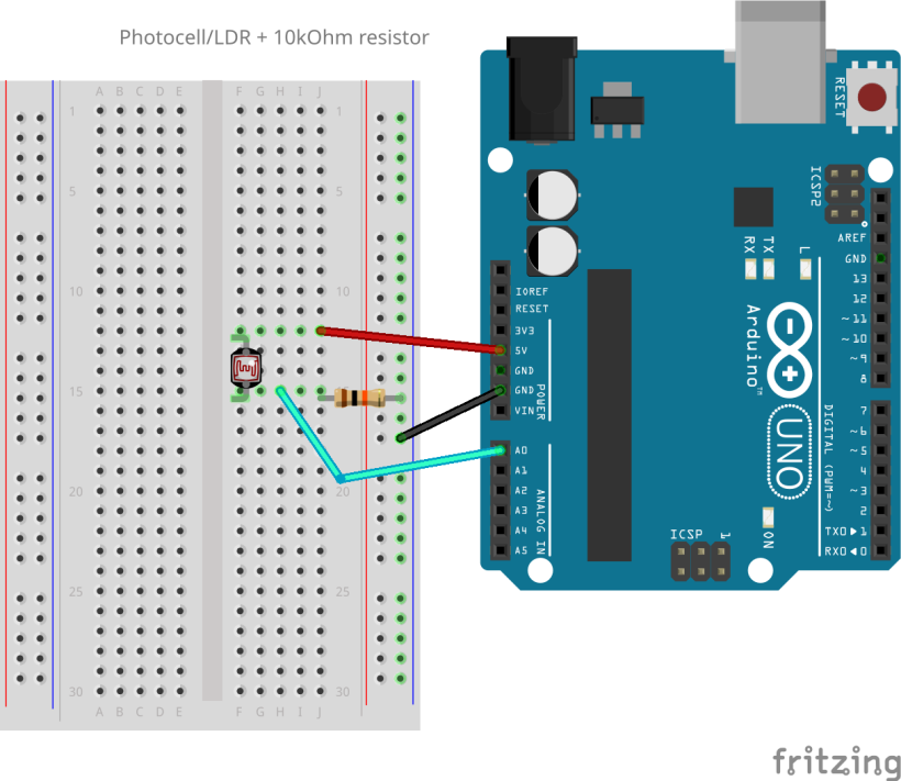
5V
│
LDR
│
●── A0
│
10kΩ resistor
│
GND
The LDR is a variable resistor and changes its resistance according to the light intesitiy. That means the point in the middle (A0 analog pin) has a voltage between 0 V and 5 V depending on the resistor values. This is where the Arduino measures the voltage and translates it into 0-1023 analog values.
#Coding an LDR
In Arduino open the example code File>Examples>01.Basics>AnalogReadSerial. Adjust your analog pin (A0-A5). Upload the code and open the Serial Monitor. You should be able to read the incoming values of the LDR now.
Relations:
bright light > low LDR resistance > high analog value
dark light > high LDR resistance > low analog value
Distance Sensor
#About distance sensors
Several types of distance sensors can be used with Arduino, each offering different features and capabilities. The most common types include:
- Infrared sensors (IR): These sensors use infrared light to detect the presence of objects and estimate their distance. They can be either reflective IR sensors (where the IR beam is reflected back to the sensor) or triangulation IR sensors.
- Laser distance sensors: Laser distance sensors use a laser beam to measure distance. They are generally more precise than ultrasonic or IR sensors, but they can be more expensive.
- Time-of-flight sensors (ToF): ToF sensors measure the time it takes for a light pulse to travel to an object and return. They are similar to laser distance sensors but typically use smaller laser beams, making them more compact and energy-efficient. Available in the LAB: the VL53L0X measures distances up to 4 meters.
- Ultrasonic sensor: These sensors emit high-frequency sound waves and measure the time it takes for the reflected sound to return. This allows them to calculate the distance to an object.
In the following the ultrasonic distance sensor HC-SR04 is explained in detail. It can measure distances up to 4 meters, operating voltage is 5V.
#Wiring an ultrasonic distance sensor
VCC -> 5V
TRIG -> Digital Pin
ECHO -> Digital Pin
GND -> GND
#Coding an ultrasonic distance sensor
#Distance without library
You can code a distance sensor without using any library for first try outs like this:
const unsigned int TRIG_PIN=1;
const unsigned int ECHO_PIN=2;
const  unsigned int BAUD_RATE=9600;

void setup() {
  pinMode(TRIG_PIN, OUTPUT);
  pinMode(ECHO_PIN, INPUT);
  Serial.begin(BAUD_RATE);
}

void loop()  {
  digitalWrite(TRIG_PIN, LOW);
  delayMicroseconds(2);
  digitalWrite(TRIG_PIN,  HIGH);
  delayMicroseconds(10);
  digitalWrite(TRIG_PIN, LOW);


  const unsigned long duration= pulseIn(ECHO_PIN, HIGH);
 int distance= duration/29/2;
  if(duration==0){
   Serial.println("Warning: no pulse from sensor");
   }
  else{
      Serial.print("distance to nearest object:");
      Serial.println(distance);
      Serial.println(" cm");
  }
 delay(100);
}#Distance with library
For more complex projects or exhibition settings you can use a library in order to get more control and more stable values. Download the "NewPing.h" library in the Library Manager in the left side bar.
// Include the library:
#include "NewPing.h"

// Define pins and max distance:
#define trigPin  2
#define echoPin  3
#define MAX_DISTANCE 350 // Maximum distance we want to ping for (in centimeters). Maximum sensor distance is rated at 400-500cm.

NewPing sonar(trigPin, echoPin, MAX_DISTANCE); // NewPing setup of pins and maximum distance.
float duration, distance;

const int ledPin = 11; // arduino pin 11 or any PWM pin
int ledLow = 0;
int ledHigh = 255;

void setup() {
  Serial.begin(9600); // Open serial monitor at 9600 baud to see ping results.
  pinMode (ledPin, OUTPUT);
  digitalWrite(ledPin, LOW);
}

void loop() {
  delay(50); // Wait 50ms between pings (about 20 pings/sec). 29ms should be the shortest delay between pings.

  duration = sonar.ping();
  distance = (duration / 2) * 0.0343;

  Serial.print("Distance = ");
  Serial.print(distance); // Distance will be 0 when out of set max range.
  Serial.println(" cm");

  if (distance<10) {
  digitalWrite(ledPin, LOW);
}
  else {
  int mapped = map (distance,10,40,ledLow,ledHigh);
  analogWrite (ledPin, mapped);
  }
}
Pressure Sensor
#About pressure sensors
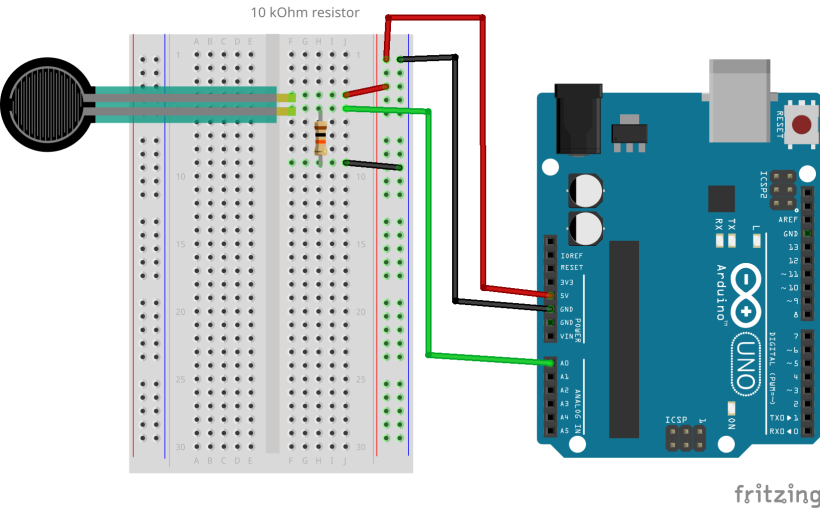
A Force Sensing Resistor (FSR), also known as a Pressure Sensor, is a simple and inexpensive sensor designed to measure physical pressure, squeeze, and weight. An FSR is simply a variable resistor whose resistance varies in response to pressure applied to the sensing area. It is made up of several thin, flexible layers. When squeezed, more of the carbon elements that normally offer resistance are brought into contact with the conductive traces, thereby lowering the resistance.
In the absence of pressure, the sensor will read infinite resistance (larger than 1MΩ). Applying more pressure to the sensor’s head reduces the resistance between its terminals, while releasing the pressure restores the resistance to its original value.
#Wiring a pressure sensor
#Coding a pressure sensor
Use analogRead(fsrpin) for measuring the applied pressure and print the values to the Serial Monitor.
Piezo Vibration Sensor
#About piezo sensors
A piezo is an electronic device that generates a voltage when it's physically deformed by a vibration, sound wave, or mechanical strain. Similarly, when you put a voltage across a piezo, it vibrates and creates a tone. Piezos can be used both to play tones and to detect tones.
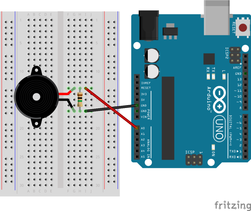
#Wiring a piezo sensor
Black pin -> GND
Red pin -> Analog Pin
Connect a 1 MOhm resistor in parallel to the Piezo element to limit the voltage and current produced by the piezo and to protect the analog input.
#Coding a piezo sensor
Open the example code File>Examples>01.Basics>AnalogReadSerial to read the analog values in the Serial Monitor.
Or use this example code to the Arduino "Knock" project File>Examples>06.Sensors>Knock to toggle an LED when hitting the piezo element.
Capacitive Sensor
#About capacitive sensors
A capacitive sensor can detect approximation or touch of the human body. To detect this approximation capacitive sensors emit an electrical field from the sensing end of the sensor. Any target that disrupts this electrical field can be detected.
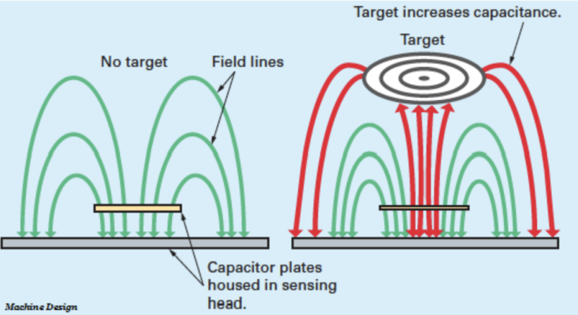
https://robu.in/capacitive-proximity-sensor-working-principle/
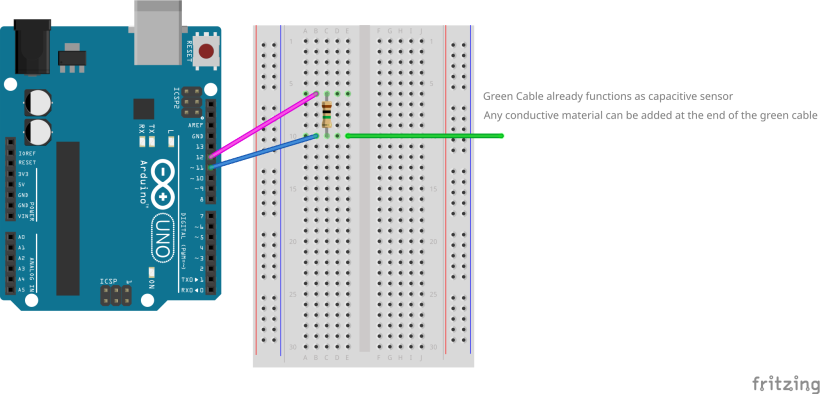
#Wiring a capacitive sensor
The green cable already functions as capacitive sensor and you will notice changing values when approaching your hand or touching it. Attach any conductive material to the end of the green cable to design your approximation sensor.
#Coding a capacitive sensor
Example code using the CapacitiveSensor.h and the Filter.h library. Download both libraries as indicated in the comments.
This code maps the sensor values to the brightness of an LED.
/*Capacitive Sensor & LED Fading
Use 1-10 MOhm Resistor for sensor, 220ohm for LED
>Don't touch your Laptop, while uploading or touching sensor!
>no power cable connected to laptop, while defining your sensor values!
>power supply through micro usb cable to power bank or socket. Lithium polymer battery doesn't work. cable works as capacitive sensor
as well and should lay as much as possible in distance
>delete serialprint when you use external power supply, it saves battery
*/

#include <Filter.h> //install library: MegunoLink
#include <CapacitiveSensor.h>; //install library: CapacitiveSensor


CapacitiveSensor capSensor= CapacitiveSensor(4,2); // arduino pin connections: pin4= connection to resistor,pin2= connecting to resistor and further to sensor

ExponentialFilter <float> FilteredTouch1(30, 0); // initializing filter with weight* 20 and initial value 0

int sensorValue = 0; // int= integer = variable
int filterValue = 0; // float= datatype for a number that has a decimal point, greater resolution than integers
const int ledPin = 11; // arduino pin 11 or any PWM pin

int ledLow = 0;
int ledHigh = 255;


void setup() {

  Serial.begin (9600);

  pinMode (ledPin, OUTPUT);
  digitalWrite(ledPin, LOW);
}

void loop() {
  int sensorValue = capSensor.capacitiveSensor(10); // small value= sensor less sensitive, bigger value= sensor more sensitive

  FilteredTouch1.Filter(sensorValue);
  filterValue = FilteredTouch1.Current();

  Serial.println(filterValue);

  if (filterValue<10) {
  digitalWrite(ledPin, LOW);
}
  else {
  int mapped = map (filterValue,10,1500,ledLow,ledHigh);
  analogWrite (ledPin, mapped);
  }


  delay(150);
}

/*
*Filter weight: This value should be between 0 and 100.

High weights (90, for example) favor new data over old data.
So, the output responds quickly to changes in the input and is not smoothed much.

Low values of (10, for example) favor old data over new data.
So, the output is heavily smoothed and the filter responds slowly to changes (noisy or not) in the input.
 */
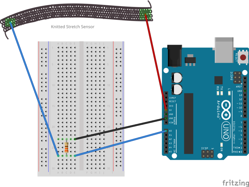
Knitted Stretch Sensor
#About textile stretch sensors
Stretch sensing works through measuring the resistance the steel yarn changes when being pulled or relaxed. This is due to the structure of the conductive yarn which is made up of lots of short steel fibers mixed with polyester. The knit structure allows you to accumulate more yarn and thus more resistance in less length. By combining conductive yarn with regular yarn (thicker/thinner) you can influence the sensitivity of the sensor. Knitting also creates a stretchy structure supporting natural tangible feedback.
#Making and wiring a stretch sensor
How to make it:
-Cut 2-3m of the grey steel yarn (not the silver yarn!), combine it with some normal yarn and knit both yarns together (tube or flat)
-Measure the resistance of your knitted stretch sensor with a voltmeter: hold both ends to the electrodes of the voltmeter and select setting Ω
Resistor calculation: I = V/ Rfix + Rsensor
Current (I) should be ≤ 10 mA to be safe for the Arduino pin.
Rsensor+Rfix ≥ V/0.01
Rsensor+Rfix ≥ 500Ω with V=5V or Rsensor+Rfix ≥ 330Ω with V= 3.3V input.
Example:
Rsensor= between 10 and 20Ω, V= 5V
Rsensor=500Ω-20Ω= 480Ω