Electronic basics
- Electronic basics
- Current, Voltage, Resistance
- Ohms Law
- Resistors
- Basic circuit
- Parallel & series circuits
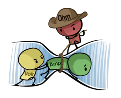
Current, Voltage, Resistance
Voltages “pushes” electrons through conductive material (e.g. a wire). The amount of electron flow is called current. Some materials are better at conducting current than others. Resistors are specially formulated to resist the flow of electrons.

More information: https://makeabilitylab.github.io/physcomp/electronics/electricity-basics.html
Ohms Law
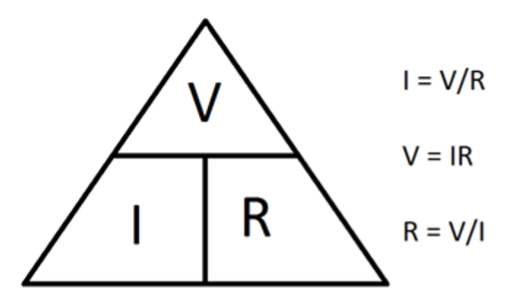
Ohms Law shows the relation between Voltage, Current and Resistance within a circuit.
The mathematical equation helps calculating unknown values:
V (Voltage) = I (Current) x R (Resistance)
Resistors
Resistors are important electrical components in digital circuits: a resistor is used to resist the flow of charge, the current, in a circuit.

Resistors have no polarity so their orientation do not matter in a circuit. Resistors are characterized by their resistance R value measured in Ohms.
How does it work? In a resistor, flowing electrons collide with atoms making them vibrate, which converts electrical energy to heat energy.
The image below shows how a resistive material (like carbon) is wrapped around an insulator and covered by a tan insulating material. The increasing number of wraps increases the length of the resistive material and thus increase resistance.

What do the colors say?
To read the resistor color bands, orient the resistor such that the “tolerance” band (e.g., the gold band for tan resistors or a brown band for blue resistors) is on the right. Then you read the color bands left-to-right based on the color chart below. Notably, the color band just before the tolerance band is a multiplier and the preceding bands are digit bands that tell you what to multiply.

More about how to calculate a resistor value within a circuit here.
More information on resistors: https://makeabilitylab.github.io/physcomp/electronics/resistors.html
Basic circuit
A basic electrical circuit is a closed path that allows electric current to flow from a power source, through components, and back to the source.
#Main Parts of a Basic Circuit
- Power Source: Provides electrical energy. Example: a battery, the arduino 5V or analog/digital pins.
- Conductors: Connect all parts of the circuit and allow electricity to flow. Example: Wires, conductive traces like copper tape.
- Load: A component that uses the electrical energy to do something (light, move, heat, etc.). Example: a Light Emitting Diode (LED) or a motor.
- Switch (optional): Opens or closes the circuit to control the current. Example: a push button.
#How it works
The battery pushes electrons from + to - through the circuit, if the push button is closed. The current flows through a resistor, which limits the current so the LED doesn’t burn out. The current then passes through the LED, causing it to light up. Finally, the current returns to the battery, completing the closed loop.
#Schematics
There are different possibilities to sketch a circuit and show its functionality. A circuit schematic shows the power supply, all electronic components and the wiring/ circuit traces connecting all these components.
In the end you could also just sketch your schematic with pencil on paper.
Programs or online tools for prototyping circuits:
Electrotechnical schematic:

Image made with Fritzing of the prototyped circuit with arduino 5V pin power supply:

Schematic of the prototyped circuit with arduino 5V pin power supply made with Fritzing :
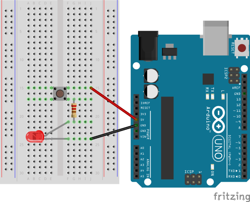
Long leg of the LED must be connected to 5V, short leg of LED is connected to GND. It does not matter where push button and resistor are being placed.
#Push Button
How a push button works:

More information: https://makeabilitylab.github.io/physcomp/electronics/schematics.html
Parallel & series circuits

More information: https://makeabilitylab.github.io/physcomp/electronics/series-parallel.html