Actuators
LEDs
#About LEDs
A light-emitting diode (LED) is basically a semiconductor device that transmits light when an electric current is given into it. Light is displayed when the particles that take the current (known as electrons and holes) mix with the semiconductor material. Since light is produced between the solid semiconductor material, LEDs are known as solid-state devices.

Through-hole LEDs have two leads: the longer one is the positive lead (anode), the shorter one is the negative lead (cathode). Through-hole LEDs have leads that are inserted through drilled holes in the circuit board and soldered on the other side, while SMD (Surface Mount Device) LEDs are soldered directly onto the surface of the circuit board without needing holes. They can be much smaller and are more difficult to solder manually.
#LED Wiring
Through-hole LEDs have two legs: the longer leg is the positive leg (anode), the shorter leg is the negative leg (cathode). The positive leg is connected to VCC (3V), the negative leg is connected to GND.
To control LEDs with Arduino, you'll need one 220ohm resistor per LED to prevent your LED from getting damaged: maximum voltage for basic LEDs is around 3V, Arduino pins supply 5V. See one possible wiring in the image below. The resistor can also be connected between GND and the negative terminal.

#Resistor calculation
The forward voltage of an LED is the minimum voltage required across the LED (anode to cathode) for it to turn on and conduct current.
Typically, this voltage varies by color:
• Red LEDs: 1.6V to 2.0V
• Green LEDs: 1.9V
• Yellow LEDs: 2.1V
• Blue LEDs: 2.4V to 3.7V
• White LEDs: 3.2V to 3.6V
• Ultraviolet LEDs: 3V
For prototyping all LED colors work with a 220Ohm resistor. For bigger projects it may be needed to calculate the precise resistor value. Here is how to calculate a resistor for e.g. a red LED:
Ohms Law: V (Voltage) = I (Current) x R (Resistance)
R = (Vsupply - Vf) / I = (5V - 2V) / 0.02A = 150 ohms per LED
• Vsupply is your supply voltage: Arduino pin output 5V
• Vf is the forward voltage of the LED: e.g. red LEDs need around 2V
• I is the current: typically 20mA for all standard LEDs
#Controlling more than one LED
The maximum number of LEDs you can control with an Arduino depends on the current draw of the LEDs (information to be found in the data sheet of the specific LEDs) and the capabilities of the Arduino board.
Generally, you can not directly connect many LEDs to a single Arduino pin due to current limitations:
The Arduino Uno itself has a total current limit of 200mA and each pin on an Arduino Uno can supply a maximum of 20mA.
If you're using standard LEDs that draw 20mA each, you could theoretically connect 10 LEDs (one per pin) but it's recommended to stay below that limit for safety and reliability.
Check out series and parallel circuits and find out possibilities how to connect more LEDs to one pin.
#Coding LEDs
File>Examples>01.Basics>Blink
File>Examples>01.Basics>Fade
File>Examples>02.Digital>BlinkWithoutDelay
Piezo buzzer
#About a piezos
A piezo buzzer is driven by voltage and is constructed out of piezoelectric material. This material mechanically deforms in response to applied voltages, which can be used to generate sounds.
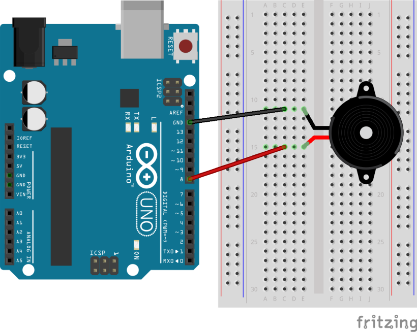
#Wiring a piezo
Leg 1 -> GND
Leg 2 -> digital pin
#Coding a piezo as buzzer
To play a sound use the tone() and noTone() functions.
tone(pin, frequency, duration);
noTone (pin);
The Arduino can generate frequencies from 31 Hz up to 65.535 Hz. The human ear can perceive frequencies ranging from approximately 20 Hz to 20,000 Hz.
Using tone() interferes with PWM output on pins 3 and 11 (on non-Mega boards).
Example Code in the Arduino IDE: File>Examples>01.Digital>ToneMelody
This example code uses the header file pitches.h, which opens in a second tab in the sketch. It contains all the pitch values for typical notes. For example, NOTE_C4 is middle C. NOTE_FS4 is F sharp, and so forth. The notes in this file range from 31Hz to 4978Hz.
To use this header file in another sketch, simply klick the three-dot-menu in the upper right corner and select "New Tab". Then copy-paste the pitches.h content from the ToneMelody example code to your new tab.
More information: https://itp.nyu.edu/physcomp/labs/labs-arduino-digital-and-analog/tone-output-using-an-arduino/
Motor
#About motors
There are three basic types of motors to control with Arduino:
DC Motors
• Continuous Rotation: DC motors spin continuously based on the applied voltage, allowing for speed control.
• Simple Control: They're relatively simple to control, requiring a voltage to determine speed and direction.
• Applications: Used in various applications like fans, pumps, and basic robotic systems.
More information: _https://wiki.dfrobot.com/Gravity__130_DC_Motor_SKU__DFR0411_
Stepper Motors
• Precise Step-by-Step Movement: Stepper motors move in discrete, precise steps, allowing for accurate position control.
• Open-Loop Control: They operate on an open-loop system, meaning they don't have feedback about their position, relying on the number of steps to maintain accuracy.
• Applications: Found in applications like 3D printers, CNC machines, and cameras.
Servo Motors
• Precise Angle Control: Servo motors rotate to a specified angle and hold that position.
• Closed-Loop Feedback: They use a closed-loop system with a position sensor to ensure they accurately reach the desired angle. • Applications: Used in robotic arms, camera pan/tilt mechanisms, and other applications requiring precise angular positioning.
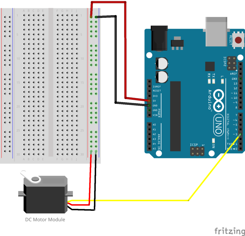
#Wiring a DC motor module
Especially for DC motors you need a motor driver with Arduino to provide the necessary power and protection for motors, as the Arduino's pins can't handle the current demands of motors.
In the LAB we provide the DF Robot Gravity 130 DC Motor Modul. You can easily and directly use the Arduino Uno to drive this DC motor module, speed control can be realized with PWM signal. The operating voltage is 5V.
Black wire -> GND
Red wire -> 5V
Yellow wire -> PWM pin.
More information: _https://wiki.dfrobot.com/Gravity__130_DC_Motor_SKU__DFR0411_
#Coding a DC motor module
The following example code changes the speed of the motor every three seconds from slow to medium to full speed.
int motorPin = 3;   // Arduino PWM pin connected to motor signal pin

void setup() {
  pinMode(motorPin, OUTPUT);
}

void loop() {
  // Slow speed
  analogWrite(motorPin, 80);
  delay(3000);

  // Medium speed
  analogWrite(motorPin, 150);
  delay(3000);

  // Full speed
  analogWrite(motorPin, 255);
  delay(3000);
}
Keypress
#About Keypress
Using the Arduino library “Keyboard.h” your code can produce a keypress, as if you were typing the character on our keyboard.
To use the Keyboard.h library you need a microcontroller with native USB adapter to send keystrokes to a connected computer, e.g. the Adafruit Trinket M0. The Arduino Uno uses a separate USB-to-serial adapter (the 16u2) for communication, not a native USB adapter.
#Adafruit Trinket M0
- Go to Arduino IDE > Preferences > Additional Boards Manager URLs and enter this URL: https://adafruit.github.io/arduino-board-index/package_adafruit_index.json
- Go to Boardsmanager (2nd icon from top on left side), search for SAMD and install:
• Arduino SAMD Boards
• Adafruit SAMD Boards
When you plug in the Board via USB cable, you should be able to select Board Adafruit Trinket M0 and Port COM-Port and upload your code.
Yes, there is the possibility to turn the very bright onboard RGB light off (default on):
#include <Adafruit_DotStar.h>

// Number of LEDs in strip
#define NUMPIXELS 1

// Here's how to control the LEDs from any two pins:
#define DATAPIN   7
#define CLOCKPIN  8

Adafruit_DotStar strip = Adafruit_DotStar(
  NUMPIXELS, DATAPIN, CLOCKPIN, DOTSTAR_BGR);

void setup() {
  strip.begin(); // Initialize pins for output
  strip.show(); // Turn all LEDs off
}

void loop() {
}#Pinout


https://learn.adafruit.com/adafruit-trinket-m0-circuitpython-arduino/pinouts
#Coding with the keypress library
ASCII stands for American Standard Code for Information Interchange. Computers can only understand numbers, so an ASCII code is the numerical representation of a character such as 'a' or '@' . You need to choose the according number from the table to define the characters in your code. See the ASCII table here.
Open a text program then upload the code and activate the text window again. After five seconds the code will type HELLO WORLD.
#include <Keyboard.h>

void setup() {
  Keyboard.begin();
  delay(5000); // Zeit damit der Computer bereit ist

  Keyboard.print('H');
  delay(3000);

  Keyboard.print('E');
  delay(3000);

  Keyboard.print('L');
  delay(3000);

  Keyboard.print('L');
  delay(3000);

  Keyboard.print('O');
  delay(3000);

  Keyboard.print(' ');
  delay(3000);

  Keyboard.print('W');
  delay(3000);

  Keyboard.print('O');
  delay(3000);

  Keyboard.print('R');
  delay(3000);

  Keyboard.print('L');
  delay(3000);

  Keyboard.print('D');
}

void loop() {
}
Short version of the above example code with a loop.
#include <Keyboard.h>

char text[] = "HELLO WORLD";

void setup() {
  Keyboard.begin();
  delay(5000);

  for (int i = 0; i < sizeof(text) - 1; i++) {
    Keyboard.print(text[i]);
    delay(3000);
  }
}

void loop() {
}